The symbol “E”
represents electromotive force (electron moving force) commonly referred to as
VOLTS or electrical pressure. The symbol “I” represents INTENSITY or current
flow in AMPERES.
The symbol “R”
represents RESISTANCE which is measured in OHMS. The symbol (Ω) for Omega, the
last letter in the greek alphabet, is used as a ohm symbol to avoid using the
letter O which can easily be mistaken for the numeral 0 (zero).
In summation: E is
volts; I is amperes; R is ohms.
The automotive
electrical system is a combination of interrelated circuits. Many of the
electrical components in a system have self-contained circuits. Diagnosing trouble
will require a knowledge of where to look when certain conditions are
indicated. The ability to trace a circuit will be of great value in pinpointing
the difficulty.
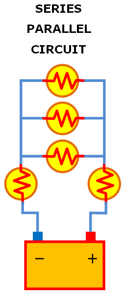
SERIES CIRCUIT:
A series circuit is a circuit where there is only one path in which the current can flow. Any number of lamps, resistance, or other devices having resistance can be used to form a series circuit. The total resistance of a series circuit is the sum of the individual unit resistances. The more resistances that are added to the circuit, the higher will be the total resistance. Since there is only one path for current to flow in a series circuit, this means that all current must pass through each resistance in the circuit. If an opening occurs in any portion of a series circuit. the circuit will become inoperative. This will result in an incomplete circuit. If one bulb burns out, it opens the circuit and the rest of the bulbs go out.
The current flow in a series circuit is controlled by the total resistance of the circuit and the voltage supplied. The current flow (amperes) will be the same in all places in the circuit. If two ammeters are connected in different places in a series circuit, both ammeters will read alike. If more resistance is added to the circuit, the amperage will become less, and if resistance is removed from the circuit, the amperage will increase.
As voltage moves current through a resistor, some of the force is expended, resulting in a loss or drop in voltage. This "voltage drop" always accompanies current moving through a resistance. Therefore, in a series circuit, the total voltage will always equal the sum of the " voltage drop" across the individual resistance units. The total voltage or the voltage across each resistance can be measured with a voltmeter, and this method called " voltage drop test" is widely used to determined circuit conditions.
PARALLEL CIRCUIT:
The circuit that has more than one path for current is called a parallel circuit. Parallel resistance connected across a voltage source have the same voltage applies to each resistance. The resistance of the individual units may or may not be the same value. Since the current divides among the various branches of the circuit, the current through each branch will vary, depending upon the resistance of the branch. However, the total current flow will always equal the sum of the current in the branches. The total resistance of a parallel circuit is always less than the smallest resistance in the circuit. If a break occurs in a parallel circuit, the circuit is not rendered inoperative because there is more than one path for current to flow back to its source. An illustration of this is street lights. If one bulb runs out, the other remain lit.
An important thing to remember in a parallel circuit is that the voltage applied remains constant at each branch.


0 Comments
Please do not enter any spam link in the comment box.